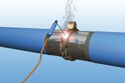
Welding pipes
Information on the production, testing and assessment of welded joints is set out in EN 12732 and in DVGW Worksheet GW 350.
The requirements to be met by the welding company, for example in relation to the quality assurance system, depend on the intended pipeline service area and the associated quality level (A to D). The welders must have passed a qualification test to EN 287-1 for the welding techniques, materials and dimensions concerned and must hold a valid examination certificate.
Suitable welding techniques, depending on the requirements and welding conditions, are manual metal arc welding (process 111 according to ISO 4063), TIG welding (process 141), metal active gas (MAG) welding (process 135) and oxy-acet welding (with oxygen-acetylene flame, process 311).
The most commonly used field welding process is manual arc welding with a coated electrode. ISO 2560 specifies the use of basic or cellulose coated electrodes. The process is used for all welding passes (root, filler and cap passes) and positions and is particularly well-suited for vertical-down welding. In addition, the good protective atmosphere is a great advantage in field welding.
Both the TIG and MAG welding processes are limited in their suitability for field welding due to the sensitivity of the protective gas atmosphere to weather influences. They are therefore more appropriate for workshop welding. Their high degree of automation makes both processes popular for orbital welding, with TIG welding also being used for root passes in view of the high weld efficiency it can achieve.
Gas fusion welding is used for pipe sizes up to DN 150 in all welding positions except vertical-down. Generally, it tends to be less commonly used because of its relatively low cost effectiveness.
Water line pipe
Water line pipes are generally welded with the same welding parameters as gas line pipes. The cement mortar lining in water line pipes means, however, that some additional points have to be considered.
Butt weld joints in particular should be executed only by manual arc or TIG (for the root pass) welding because of the lower heat input.
When water line pipes are joined by manual arc welding with cellulose-coated electrodes, an ISO-2560-compliant E 42 2 C 25 electrode is used (e.g. Thyssen CEL 70 up to 360 N/mm2 yield strength).
In order to limit the heat input, the root pass must be welded at the minus pole using the lowest possible welding current. The lower pipe sections (i.e. from the 3 o’clock to the 6 o’clock and from the 9 o’clock to the 6 o’clock positions) should be welded first and only then the upper half of the pipe. Filler and cap passes are welded from 12 to 6 o’clock.
Making up a welded joint
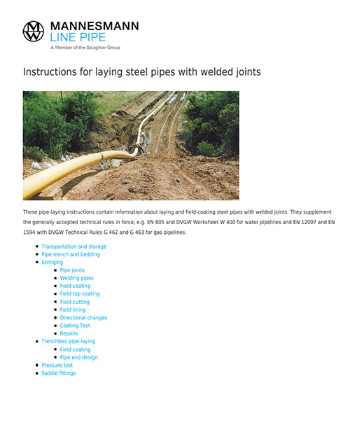
1. Before welding, the edges must be cleaned to remove any surface protection, rust and dirt. This includes removing the coating (complete with adhesive) over an area of 10 times the wall thickness, or at least 100 mm.
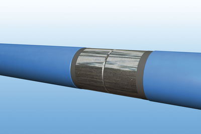
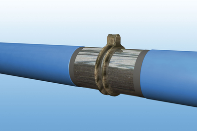
2. Couplings (in pipes with slip welding joint) and collars (in pipes with sleeve joint) must be heated to forging temperature if necessary and the entire circumference prepared over a length of at least 30 mm in such a way that the gap at the root is kept as small as possible (tight fit).
3. Install the centering device. For pipes up to about DN 300, external line-up clamps should be used. This allows the entire root pass to be welded without loosening the clamps. For larger pipe sizes and wall thicknesses, it may be advisable to use a pneumatic or hydraulic internal centering device.
4. Depending on the welding conditions and the pipe material used, the pipe ends may have to be preheated as specified in the welding instructions.
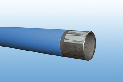
5. Welding the pipe ends: The weld area must be kept free of detrimental influences (e.g. dust, dirt, grease and water) and protected from rain and wind. The welds must be executed in a minimum of two passes (single-pass welds are permissible in the case of gas fusion welding up to a pipe wall thickness of about 3.6 mm). Welding must be performed swiftly and without any significant interruptions up to the cap pass.
Recommended welding current as a function of the electrode diameter:
| Electrode diameter (mm) | Current (A) | |
| Root pass | 2.5 bzw. 3.2 | 50-80 bzw. 80-130 |
| Filler or cap pass | 4.0 | 120-180 |
Gas line pipe
The recommendations for the welding of water line pipes also apply to gas line pipes. However, when welding higher-strength grades as per ISO 3183 in particular, account must be taken of the specific alloy properties and processing behavior.
The welding parameters and the required post-weld measures, e.g. protection against humidity, must be adapted to the material thickness, heat input and preheating temperature and defined accordingly in the welding instructions.